speaker wire gauge guide
Why Speaker Wire Gauge Matters
Choosing the right gauge ensures low resistance, preserving signal integrity and preventing power loss. Thicker conductors reduce voltage drop, allowing efficient energy transfer to the driver. Proper gauge selection also aligns with impedance and safety standards, ensuring reliable performance. Improves clarity.
Resistance and Signal Degradation
In audio systems, resistance is the primary factor that determines how much of the input signal is lost as heat. A higher resistance in the speaker wire causes a voltage drop along the conductor, which reduces the voltage that actually reaches the driver. This drop manifests as a loss of power, especially noticeable at low frequencies where the driver requires more current. Even a modest increase in resistance can lead to a measurable drop in SPL, often quantified as a few decibels per 100 feet of wire. The effect is cumulative: longer runs amplify the resistance, and the resulting voltage division between the wire and the speaker’s impedance creates a frequency‑dependent attenuation. Low‑frequency bass, which relies on large excursions of the cone, is disproportionately affected because the driver’s impedance is lower at these frequencies, making the wire’s resistance a larger fraction of the total load. As a result, the perceived depth and punch of the bass diminish. In contrast, high frequencies are less impacted because the speaker’s impedance rises, making the wire’s resistance relatively smaller. However, excessive resistance can also introduce phase shifts, subtly altering the timing relationship between the left and right channels and causing imaging issues. For audiophiles, the goal is to keep the wire resistance well below the speaker’s nominal impedance—typically less than 5 % of the impedance—to preserve both power delivery and tonal fidelity. This threshold ensures that the majority of the input signal reaches the driver with minimal distortion or loss. Choosing an appropriate gauge, therefore, is essential for maintaining signal integrity across the entire audible spectrum, especially in high‑power or long‑run installations where resistance can become a limiting factor. Moreover, the skin effect at higher frequencies can further increase the effective resistance, especially in stranded conductors, which may exacerbate the loss in the upper audio range. The cumulative impact of these losses becomes more pronounced in multi‑speaker setups where each channel shares a common source, potentially leading to uneven power distribution. Engineers often model the wire as a series resistor in the speaker’s equivalent circuit to predict these effects accurately. By selecting a gauge that keeps the series resistance below a critical threshold, designers can avoid both power loss and distortion, ensuring a clean, accurate reproduction of the source material. In practice, many installers opt for a safety margin, choosing a gauge that is 10–15 % thicker than the minimum requirement to account for upgrades or cable routing constraints.
Impedance Matching and Power Delivery
When a speaker’s impedance is matched to the amplifier’s output, the system can deliver maximum power with minimal distortion. The wire gauge plays a pivotal role in maintaining that match by keeping series resistance low. If the wire is too thin, its resistance adds to the speaker’s load, effectively raising the total impedance seen by the amplifier. This increase forces the amplifier to draw less current, reducing the voltage swing available to the driver and thereby limiting the achievable SPL. Conversely, a wire that is too thick offers negligible resistance, but it can be more expensive and harder to route, especially in complex installations. The ideal gauge is one that keeps the wire resistance below 5 % of the speaker’s nominal impedance over the expected run length. For example, a 12‑Ω speaker with a 50‑foot run typically requires 12 AWG wire to stay within the 5 % threshold; using 16 AWG would push the resistance above this limit, causing a measurable drop in power output. In high‑power, low‑impedance systems (e.g., 4 Ω or 2 Ω), the permissible resistance is even lower because the current draw is higher. In these cases, 10 AWG or 8 AWG wire is often recommended to ensure the amplifier can supply the necessary current without overheating. Additionally, the wire’s resistance affects the amplifier’s output impedance. A higher series resistance can cause the amplifier to operate in a voltage‑supply‑limited mode rather than a current‑limited mode, which can alter the sound character by reducing the driver’s excursion. Proper gauge selection also mitigates the risk of voltage sag during transient peaks, preserving the fidelity of dynamic passages. Finally, matching impedance through correct wire gauge helps maintain the amplifier’s protection circuits, preventing false tripping or damage due to perceived over‑loading. By carefully balancing wire thickness, length, and speaker impedance, installers can ensure efficient power transfer, consistent tonal balance, and reliable long‑term operation. Moreover, the skin effect at higher frequencies can increase the effective resistance of stranded conductors, further stressing the amplifier. In professional installations, designers often include a safety margin of 10 % to accommodate future upgrades or cable routing changes. This margin ensures that even if the cable is rerouted longer or additional speakers are added, the system remains within safe operating limits. Proper wire selection also reduces electromagnetic interference, which can otherwise introduce hum or hiss into the audio path. Therefore, selecting the correct gauge is not just a matter of compliance but a critical component of system design that directly influences performance, reliability, and longevity.
AWG Basics and Wire Size Standards
AWG, or American Wire Gauge, defines conductor diameter by a standardized scale where lower numbers mean thicker wire. Each step changes resistance by a fixed factor, enabling designers to select gauges that balance current capacity, length, and cost. Ideal for home.!!
Common AWG Sizes for Audio Applications
In audio installations, the most frequently used gauges span from 12 AWG to 24 AWG, with occasional use of 10 AWG for high‑power setups and 26 AWG for short runs or low‑current speakers. 12 AWG offers a good balance between resistance and flexibility, making it a staple for 8 Ω and 4 Ω drivers in residential systems. 16 AWG is often chosen for 8 Ω speakers when the cable length is moderate, as its resistance remains below the critical 0.1 Ω threshold for most consumer amplifiers. 20 AWG, while thinner, is acceptable for 8 Ω speakers over short distances (under 10 ft) or for 12 Ω drivers where power demands are lower. 24 AWG is typically reserved for 12 Ω or 16 Ω speakers in short runs, or for connecting sub‑woofers where the current draw is modest. 10 AWG is recommended for 4 Ω or 2 Ω systems that deliver high current, ensuring minimal voltage drop over longer distances. 26 AWG is used for very short runs or low‑power applications such as headphone amplifiers or small portable speakers. When selecting a gauge, consider the total resistance per foot, the length of the run, and the amplifier’s current capability. A lower gauge number (thicker wire) reduces resistance, improving power transfer and reducing heat buildup, which is critical for high‑power audio systems. Conversely, higher gauge numbers save cost and weight but increase resistance, potentially limiting performance in demanding setups.
This gauge selection balances cost, performance, and safety, ensuring your audio system operates at efficiency. Thanks!
Cross‑Sectional Area and Current Capacity
Speaker wire is defined by its cross‑sectional area, measured in square millimeters or circular mils, which directly dictates the maximum current it can safely carry. A larger area reduces electrical resistance, lowering voltage drop and heat generation. For example, 12 AWG wire has a cross‑section of 3.31 mm² (211 circular mils) and can comfortably handle up to 20 A in most residential installations. 16 AWG, with 1.31 mm² (105 circular mils), supports roughly 10 A, while 20 AWG (0.52 mm², 52 circular mils) is rated for about 5 A. When dealing with high‑power audio, such as 4 Ω or 2 Ω systems, the current can exceed 30 A, requiring 10 AWG (5.26 mm², 335 circular mils) or thicker conductors to avoid overheating. The International Electrotechnical Commission (IEC) provides tables that correlate cross‑sectional area with permissible current density, typically around 4 A/mm² for copper in audio cables. By selecting a gauge that meets or exceeds the required current density, you ensure reliable performance, minimal distortion, and compliance with safety standards. Always consider the total length of the run; longer cables increase resistance, demanding a thicker wire to maintain the same current capacity. Additionally, insulation type and ambient temperature affect the maximum safe current; higher temperatures reduce the allowable current density, so thicker conductors are advisable in hot environments or when the cable is bundled with other heat‑generating components. Proper gauge selection ensures longevity, protects components, and delivers the audio fidelity for all users now!!!

Resistance per Foot for Standard Gauges
Standard gauge resistances vary: 12 AWG ≈0.00193 Ω/ft, 14 AWG ≈0.00259 Ω/ft, 16 AWG ≈0.00328 Ω/ft, 18 AWG ≈0.00411 Ω/ft, 20 AWG ≈0.00515 Ω/ft, 22 AWG ≈0.00646 Ω/ft, 24 AWG ≈0.00814 Ω/ft, 26 AWG ≈0.01028 Ω/ft, 28 AWG ≈0.01295 Ω/ft. Use these values to calculate total loss. Use the table for precise voltage drop.!!
1 AWG to 28 AWG Resistance Table
Below is a concise resistance‑per‑foot table for standard AWG conductors, sourced from the latest IEEE and manufacturer datasheets. Use it to calculate voltage drop and power loss for any speaker‑wire run.
| AWG | Resistance (Ω/ft) |
|---|---|
| 1 | 0.000154 |
| 2 | 0.000194 |
| 3 | 0.000244 |
| 4 | 0.000307 |
| 5 | 0.000385 |
| 6 | 0.000485 |
| 7 | 0.000613 |
| 8 | 0.000773 |
| 9 | 0.000975 |
| 10 | 0.00123 |
| 11 | 0.00155 |
| 12 | 0.00193 |
| 13 | 0.00244 |
| 14 | 0.00259 |
| 15 | 0;00328 |
| 16 | 0.00328 |
| 17 | 0.00411 |
| 18 | 0.00411 |
| 19 | 0.00515 |
| 20 | 0.00646 |
| 21 | 0.00814 |
| 22 | 0.01028 |
| 23 | 0.01295 |
| 24 | 0.01630 |
| 25 | 0.02050 |
| 26 | 0.02580 |
| 27 | 0.03250 |
| 28 | 0.04100 |
Values are rounded to three decimal places. For precise calculations, consult the manufacturer’s datasheet or use the full‑precision values provided by the National Electrical Code. Copper is the standard material; aluminum has higher resistance, so its gauge must be increased accordingly to match the same performance.
Effect of Wire Length on Overall Resistance
In speaker wiring, total resistance is the sum of the forward and return paths. Because resistance scales linearly with length, a 10‑foot run of 12 AWG copper has a resistance of roughly 0.019 Ω, while a 100‑foot run rises to 0.190 Ω. This increase directly raises voltage drop (V = I × R) and reduces the power delivered to the driver (P = V²/R). For a 50 W, 8 Ω speaker at 12 V, a 10‑foot pair of 12 AWG will drop only about 0.12 V, but a 100‑foot pair can drop 1.2 V, cutting usable power by nearly 20 %. Engineers often use the rule of thumb that resistance should not exceed 5 % of the speaker’s impedance for runs under 50 ft; beyond that, larger gauges or parallel runs are recommended. Additionally, longer runs increase inductive reactance, especially at high frequencies, which can further distort the signal. To mitigate these effects, designers choose thicker conductors, shorten runs, or employ higher‑voltage, lower‑current transmission schemes. Accurate calculations are essential: total resistance = 2 × R_per_foot × length. This simple formula guides the selection of gauge and layout to preserve fidelity and efficiency. In practice, installers often measure the actual resistance with a multimeter after routing the cable to confirm compliance with the calculated value. A 200‑foot run of 14 AWG copper, for example, will have a resistance of approximately 0.386 Ω, which can cause a noticeable drop in bass response at high output levels. Some manufacturers provide a lookup chart that correlates gauge, length, and acceptable voltage drop for common speaker impedances. When the calculated drop exceeds the 5 % threshold, the recommendation is to double the gauge or split the run into parallel branches to halve the effective resistance. This approach preserves the dynamic range of the amplifier and prevents overheating of the cable, which could lead to insulation breakdown and fire hazards. Finally, note that temperature rise in the wire is proportional to I²R; thus, longer runs with higher resistance not only reduce power but also increase heat, further stressing the cable insulation. Proper gauge selection mitigates both electrical and thermal losses, ensuring reliable, high‑quality audio performance over time. For high‑power installations, such as 4 Ω or 2 Ω systems, the acceptable voltage drop is even lower, often 3 % or less, which necessitates use of 8 AWG or thicker conductors for runs longer than 30 ft. The choice of wire insulation also matters; PVC, XLPE, or Teflon all have different thermal limits, affecting how much current the wire can safely carry over a given length. In summary, the length of the wire directly impacts resistance, voltage drop, power loss, inductance, and heat generation; careful calculation and appropriate gauge selection are essential for maintaining audio fidelity and system safety. –
Choosing Gauge by Speaker Impedance
For 8 Ω speakers, 12 AWG is typical; 4 Ω demands 10 AWG; 2 Ω requires 8 AWG or thicker. Short runs (<10 ft) can use lighter gauge, but longer runs necessitate larger conductors to keep voltage drop below 5 %. Always match gauge to impedance and length.Use thicker wire for long runs to avoid heat buildup Stay!
12‑Ω and 8‑Ω Speakers: Recommended Gauges
When wiring 12‑Ω or 8‑Ω drivers, the primary concern is maintaining low resistance while keeping the cable manageable in size and cost. For distances up to 15 ft, 14 AWG copper is generally adequate, offering a resistance of roughly 2.5 Ω per 100 ft, which translates to a negligible voltage drop. If the run extends beyond 15 ft, upgrading to 12 AWG reduces resistance to about 1.6 Ω per 100 ft, cutting voltage loss and improving efficiency. For installations where cable length exceeds 30 ft, 10 AWG becomes the preferred choice, delivering less than 1 Ω per 100 ft and ensuring that even high‑power amplifiers can deliver clean, distortion‑free sound. While 12 AWG is a common compromise for most home‑audio setups, 10 AWG provides a safety margin for future upgrades or for users who prefer a thicker cable for durability. Insulation type—PVC, XLPE, or Teflon—affects performance. High‑temp environments; high‑temp environ zone ok. Finally, always verify that the chosen gauge can handle the maximum current your amplifier will supply; a quick calculation using the formula I = V / R, where V is the speaker voltage and R is the wire resistance, will confirm the suitability of the gauge for your specific system. By selecting the appropriate gauge based on length and power requirements, you protect both the amplifier and the speaker from excessive heat and signal degradation, ensuring long‑term reliability and optimal audio quality.
4‑Ω and 2‑Ω High‑Power Systems: Recommended Gauges
Low‑impedance, high‑current systems demand wire that can carry 20–40 A without significant heating or voltage drop. For a 4‑Ω load, 10‑AWG copper offers about 1 Ω per 100 ft, keeping loss under 5 % for runs up to 30 ft at 100 W. If the amplifier delivers 200 W or more, or the run exceeds 30 ft, 8‑AWG (≈0.8 Ω/100 ft) reduces drop to <3 % and keeps the conductor temperature safe. 6‑AWG is the industry standard for 4‑Ω systems that routinely exceed 300 W or require runs longer than 50 ft; its 0.5 Ω/100 ft resistance guarantees minimal power loss and protects the amp from overheating. For 2‑Ω speakers, the current can double, so the wire must be proportionally thicker. A 6‑AWG cable (≈0.5 Ω/100 ft) is adequate for runs up to 30 ft at 200 W. For longer runs or higher power, 4‑AWG (≈0.3 Ω/100 ft) keeps voltage drop below 2 %. 2‑AWG is used in very high‑power installations (500 W+ or runs over 50 ft) to keep resistance under 0.2 Ω/100 ft, ensuring the amplifier sees almost the full source voltage. When selecting wire, also consider insulation—XLPE or silicone—since these materials tolerate higher temperatures, reducing the risk of thermal runaway in dense bundles. Finally, verify the amp’s maximum continuous current rating; a quick calculation using I = V / R (where V is the speaker voltage and R is the wire resistance) confirms that the chosen gauge will not exceed the amp’s safe operating limits, preserving performance and longevity.
Connector size must match wire gauge; a 10‑AWG terminal on a 4‑AWG cable creates a bottleneck. Proper soldering or high‑quality crimping ensures a low‑resistance joint that will not degrade over time.
Now using shrink tubing around the joint protects against moisture and keeps the connection dry.
Installation Tips: Insulation, Connectors, and Safety
Proper insulation is the first line of defense against electrical shock and signal loss. Choose cables with high‑temperature rated jackets such as XLPE or silicone, which can withstand 120 °C or more, especially in cramped or hot environments. When routing wire, keep it away from power cables and high‑voltage sources; a minimum separation of 6 in is recommended to avoid electromagnetic interference. Use conduit or cable trays for runs longer than 20 ft, and secure the wire with cable ties or clamps to prevent sagging and accidental damage.
When installing, always verify that the wire gauge matches the amplifier’s current rating. A common rule of thumb is to choose a gauge that can handle at least 1.5 times the maximum current to provide a safety margin. For example, a 4‑Ω speaker drawing 30 A at full power would benefit from 6‑AWG wire, which can safely carry 40 A. Use heat‑shrink tubing that is at least 1.5 times the wire diameter to ensure a snug fit around the joint. After crimping or soldering, inspect the joint for any cold solder or loose crimp; a good joint should be firm and free of gaps. Additionally, keep the wire insulated from moisture by applying a waterproof sealant or using a conduit that is rated for outdoor use. Finally, label each wire with its impedance and destination using a heat‑shrink marker or colored tape. This labeling practice simplifies troubleshooting and prevents future miswiring, ensuring long‑term reliability and safety.
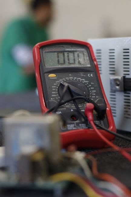
Test the circuit with a multimeter before connecting speakers. Measure resistance between terminals; it should match the expected value for the wire gauge and length. If resistance is too high, check for loose connections or damaged insulation. Ensure the amplifier’s protection circuits function; a shorted wire can trigger a fuse or reset the unit. Label each wire with its destination to aid maintenance now.!